
Search results for: “installing a subsurface drip irrigation system for row crops”
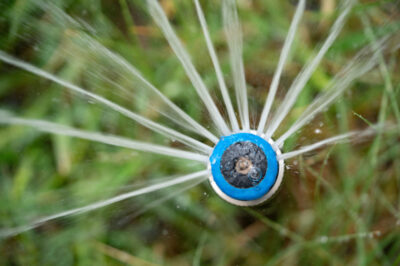
- PublicationA subsurface drip irrigation system should last more than 20 years if properly maintained. Important maintenance procedures include cleaning the filters, flushing the lines, adding chlorine and injecting acids. Details...
- PublicationA subsurface drip system distributes wastewater to the lawn through a system of tubing installed below the ground. This publication explains the advantages and disadvantages of subsurface drip distribution systems,...
- PublicationFarmers can increase yields and net returns by installing artificial drainage systems on soils that have poor natural drainage. This publication explains why artificial drainage is needed on some soils,...
- PublicationThis publication explains why artificial drainage is needed on some soils, the types of drainage systems, drainage design considerations, and the steps and economics in installing a relief drainage system....
- PublicationThe growing interest in wildlife photography has created opportunities for landowners. By installing well-placed, properly constructed blinds as an aid to photographers, landowners can establish new enterprises for wildlife conservation...
- PublicationHoney bees can be purchased through a beekeeper and sold in two forms: packages and nucleus colonies. Purchasing bees allows more control over the genetics of the colony, and the...
- Program...Irrigation Auditors. The School of Irrigation provides irrigation education through a variety of in-person and self-paced educational courses across the state to meet the changing needs of the irrigation industry....

- Publication...pivot; low energy precision application center pivot; and subsurface drip irrigation. Included is information on costs, benefits and other factors that should be considered. (20 pp., 20 tables, 9 figures)...
- PublicationChoosing and buying an irrigation system for crop production can be expensive and complex. This publication discusses five common types of irrigation systems used in Texas: furrow (or surface); mid-elevation...
- PublicationSurge flow irrigation has the potential to increase furrow irrigation efficiencies to levels usually associated with sprinkler and drip irrigation systems. This publication explains how to configure and operate surge...